
CNC Machining Services Tolerances and Surface Finishes: What Is Realistic to Specify
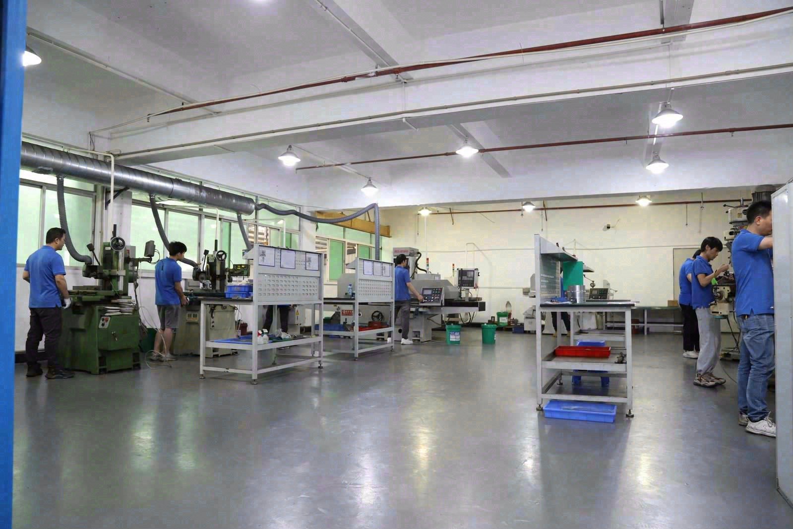
On a CNC machining services quote, the tolerance and the surface finish are where a drawing stops being a description and becomes a bet. Specify a realistic band and the machine holds it as a routine result; push a dimension to the edge of what the process can do and the price climbs, the schedule stretches, and the risk of a rejected batch migrates to you. The same is true of surface finish: a machined face at Ra 3.2 µm is a byproduct of the cut, while Ra 0.8 µm is a deliberate second operation with its own cost. This guide is about the realistic part of that equation, which tolerances a CNC machining service can actually hold by process, which finishes are routine versus expensive, how geometry and material move every number, and how to verify that what was promised is what ships. It is written for the buyer who wants to specify honestly the first time, because on an overseas order, a specification mistake is paid twice: once in the quote and once when the parts fail to fit.
Why does "what tolerance can you hold?" have a different answer on every feature?
The question sounds like it should have one answer, and every supplier wants to give you one. The honest answer is that a machining service holds different tolerances on different features, because tolerance is not a property of the machine — it is a property of the feature, the process, and the geometry around it. A flat face on a solid block holds a tighter band than the same face on a thin-walled pocket, because the wall flexes under the cutter. A bore on a rigid housing holds position differently from a bore at the end of a long cantilevered feature. A turned diameter on a short, stiff shaft holds roundness more easily than a long slender pin, which whips under cutting force.
That is why a capable shop quotes tolerance by feature, not by a single number on a brochure. The useful question is not "can you hold ±0.003 mm?" but "which features on my drawing are in the ±0.003 mm class, and which need a looser band because of geometry?" A supplier that answers feature by feature is reading your drawing; one that answers with a single capability number is quoting from a website. The DFM review before quoting exists to have exactly this conversation — to flag the features where the requested tolerance is fighting the geometry before either of you pays for the fight.
Which tolerances can a CNC machining service actually hold, by process?
Different processes land in different tolerance bands, and the band is set by how the process removes material and holds the work. The practical ladder for a CNC machining service runs like this:
| Process | Held tolerance | Typical use |
|---|---|---|
| CNC milling | ±0.003 mm | Housings, brackets, prismatic parts |
| CNC turning | ±0.003 mm | Shafts, pins, bushings, round parts |
| Precision grinding | ±0.002 mm | Bearing seats, roundness-critical surfaces |
These are production tolerances held to process capability — at the factory behind this site, Ppk ≥ 1.67 at the initial study on key characteristics and ≥ 1.33 on general ones, with a representative length characteristic running at Cpk 1.851 — not best-case claims. The practical meaning: ±0.003 mm is a routine milling-and-turning result that the process holds across a run, and ±0.002 mm is the grinding class for surfaces where roundness and seating matter. When a drawing calls out a dimension tighter than the process reliably holds, the shop should say so in the DFM review rather than quoting a hope.
Read the tolerance band before you read the index. Cpk is a ratio of the tolerance band to the process spread, not an absolute measure of accuracy. The figure above was recorded on a length characteristic with a 0.4 mm band (76.1–76.5 mm) — wide by design. Hold the same process spread against a ±0.005 mm feature and it fails outright. Ask for the band, the subgroup count and the sampling window on every capability number a supplier quotes.
When does a feature leave the machining family and move to grinding?
The move from machining to grinding is driven by the tolerance and the surface requirement together, not by either alone. A milled or turned feature can hold ±0.003 mm with a good finishing pass; holding ±0.002 mm on a bearing seat or a roundness-critical surface is a grinding operation, because grinding removes material with a bonded abrasive wheel that cuts finer and produces a more consistent surface than a single-point tool.
The signal that a feature belongs in the grinding class is usually a combination: a tight diameter or flatness callout on a surface that must seat, seal, or spin against another part. A bearing journal, a seal face, or a reference surface that other features are measured from — these are the grinding candidates. The schedule consequence is real: grinding is a separate operation with its own setup, which is one reason a part that needs a ground surface costs more and takes longer than the same geometry machined only. The DFM review should tell you which of your features, if any, actually need the grinding class, because a surface that merely touches can often live at the milled tolerance and save the operation entirely.
Which surface finishes should a custom-machined part actually specify?
Ra, the arithmetic average of the surface profile in micrometres, is how machined finish is specified, and the honest ladder beneath it is short. Every step down the scale is a different operation rather than a slower version of the previous one, which is why the cost climbs the way it does:
| Ra target | How it is reached | Total-cost note |
|---|---|---|
| Ra 3.2 µm | Standard milling or turning | Comes with the base operation; no added cost |
| Ra 1.6 µm | Fine feed, finishing pass | Slight speed penalty; standard for general engineering parts |
| Ra 0.8 µm | Fine turning or surface grinding | A second, slower operation; used for mating and sealing faces |
| Ra 0.4 µm and below | Cylindrical or precision grinding, sometimes lapping | Steep cost and lead-time step; reserved for bearing and spindle surfaces |
The buying rule is to specify the Ra the function actually requires and let the rest ride the as-machined surface. A structural bracket face that nobody touches does not need a finish callout at all; a sealing face or a bearing seat does. On an overseas order the cost note matters doubly, because each finish step adds lead time as well as price, and a part that needs Ra 0.8 µm is a part that has left the fast delivery tier behind.
How do material and geometry move what a machining service can hold?
Tolerance and finish numbers are printed on a drawing as if they were material-independent, and the first overseas order teaches every buyer that they are not. Material changes the machining behavior: aluminum cuts fast and holds a clean finish easily, stainless work-hardens under the tool and needs sharper edges and disciplined feeds, and a soft plastic deflects under the cutter in a way that no metal does. The same Ra callout is routine in aluminum and a real achievement in stainless; the same ±0.003 mm band holds comfortably in a rigid alloy and drifts in a soft one.
Geometry moves the numbers just as much. A thin wall deflects under cutting force, so the tolerance it can hold is looser than the tolerance on a solid boss. A deep pocket forces a long-reach tool that flexes, so the floor and walls of the pocket hold looser than an open face. A long slender shaft whips in turning, so its straightness and diameter tolerance must be set with the length in mind. The practical approach is to hold tight callouts on the features that carry function — bores that receive mating parts, sealing faces, locating surfaces — and give the thin, deep, or slender features the band the geometry can actually deliver. A drawing that tightens everything equally does not buy more precision; it buys inspection time, slower feeds, and scrap risk on features that did not need it.
Two feature classes deserve special mention because they quietly break across a run. The first is positional tolerance between faces: a bore on one face and a slot on another hold their relationship only if the part is machined in a way that keeps both in one reference frame, which is why re-fixturing between operations is where tolerance error gets introduced. The second is the finish on internal corners and intersections: a burr left where a cross-hole meets a bore is a quality defect no surface-finish callout catches, because Ra is measured on open faces, not inside intersections. If your part has features that trap burrs, the drawing should call out deburring explicitly rather than assuming the finish note covers it.
Tolerance, finish, and total cost are the same decision read three ways. On an overseas order the cost of an unrealistic callout is not just the premium in the quote — it is the rejected batch, the return freight, and the weeks of schedule lost while the parts come back. That is why the realistic specification question belongs before the purchase order, not after the inspection failure. The main CNC machining services total-cost guide on this site walks the full landed-cost model, including how tolerance and finish price into the number; this guide is the specification side of the same decision, the part that decides which numbers are worth putting on the drawing in the first place.
How do you state tolerance and finish on the drawing so the quote matches the part?
A drawing that leaves room for interpretation forces the shop to price the worst plausible reading, and that conservatism shows up in the quote. Three habits narrow the ambiguity before it costs you:
- Use ISO 2768 for everything you did not call out individually. The general tolerance note — ISO 2768-m for medium, ISO 2768-f for fine — sets the band for every untoleranced dimension, so the machinist does not guess whether a non-critical edge can be ±0.1 mm or ±0.5 mm. The note does the work of a hundred small callouts, and it keeps the price honest by defining what "everything else" means.
- Call out the functional features only, with the process in mind. Name the bores, sealing faces, and locating surfaces that need the tight band, and let the general note carry the rest. Each extra tight callout adds a finishing pass and an inspection step on that surface, so the cheapest finish improvement is deleting the callout that carries no function.
- State the finish where it matters, and name the treatment. Write Ra values with their parameter on the surfaces that need them, and say whether the part will be anodized, passivated, or plated. A part that will be coated can sometimes accept a slightly rougher machined finish because the coating builds on it; a bare-metal part needs the finish machined in. The drawing should say which world the part lives in.
A drawing that follows these three habits is a drawing a shop can quote accurately the first time, which is the entire point when the shop is on the other side of an ocean and every clarification round-trip costs days.
What evidence should arrive with the parts to prove the tolerance and finish?
A tolerance on a drawing is a promise until it is measured, and on an overseas order the measurement report is the only proof you will see before the parts land on your dock. The evidence set that closes the loop runs like this:
- A first-article inspection report. The first production part is measured against every drawing callout, and the report names the drawing revision, the inspector, the date, and the measurement temperature. A report that can be understood by someone who was not in the room is a report worth keeping.
- CMM results on the critical features. A coordinate measuring machine probes the finished part and compares measured coordinates against the drawing — the factory behind this site verifies critical dimensions on Hexagon CMMs. Ask which features were measured and which were assumed.
- Process-capability evidence where it matters. SPC data across the batch, with Cpk at 1.67 or higher on key characteristics, is what turns "the first article measured right" into "the process stays right." On a tolerance that carries function, ask for the capability record, not only the first measurement.
- A surface-finish measurement where a fine Ra was specified. A profilometer reading on the sealing or mating face proves the finish was reached rather than assumed. Ask which instrument measured it and on which surface.
The factory's own quality control process explains how machined parts are measured and documented before shipment, and the machined parts guide walks the tolerance-by-process detail on the parts side of the same question. On an overseas order, the measurement report is not paperwork — it is the acceptance test you would otherwise run on arrival, performed at the source where rework is still cheap.
Frequently Asked Questions
What is the smallest tolerance a CNC machining service can hold?
±0.003 mm on critical milled and turned features, verified by in-house CMM inspection, with precision-ground surfaces such as bearing seats and seal faces taken to ±0.002 mm. These are production tolerances held to process capability — Ppk ≥ 1.67 at the initial study on key characteristics and Cpk ≥ 1.33 on general characteristics. Capability is reported per characteristic: every report names the feature, its tolerance band, the sample size, the sigma method, and the study window., not best-case single-part results.
Why does a tighter tolerance cost so much more?
Because tolerance prices like a staircase, not a slope. A loose tolerance falls inside the machine's natural capability and needs no special attention; a tight tolerance forces slower feeds, more setups, better tooling, and a higher scrap rate as the process edges toward its limit. The cost is paid in time and rejected parts, not in material.
Can a milled part hold the same tolerance as a ground part?
No. Milling and turning hold ±0.003 mm as a routine result; ±0.002 mm on a bearing seat or roundness-critical surface is a grinding operation, because grinding removes material with a bonded abrasive wheel that cuts finer and more consistently. A feature that needs the grinding class is one that must seat, seal, or spin against another part.
Which surface finish should I specify for a sealing face?
A sealing or mating face typically needs Ra 0.8 µm or finer, reached by fine turning or surface grinding — a second, slower operation with real cost and lead-time consequences. A structural face that nobody touches does not need a finish callout at all; the cheapest finish improvement is deleting the callout that carries no function.
What does ISO 2768-m mean on my drawing?
It is the general tolerance reference. Everything not individually toleranced defaults to the ISO 2768 class named — m (medium) allows about ±0.1 mm on a 6–30 mm dimension and ±0.3 mm on a 30–120 mm one, while f (fine) is tighter and c (coarse) is looser. Naming the class lets the shop machine "everything else" without a quote-back question.
Can material choice make a tolerance easier or harder to hold?
Yes. Aluminum cuts fast and holds a clean finish easily; stainless work-hardens under the tool and needs sharper edges and disciplined feeds; soft plastics deflect under the cutter. The same Ra callout is routine in aluminum and harder in stainless, so the drawing should be read with the material's machining behavior in mind.
How do I know the supplier actually held the tolerance before the parts ship?
Ask for the evidence: a first-article inspection report naming the revision, the inspector, and the measurement temperature; CMM results on the critical features; SPC data showing Cpk at 1.67 or higher on key characteristics; and a surface-finish measurement where a fine Ra was specified. A supplier that produces these on request is running the process the quote assumed.
Want a tolerance and finish plan that matches what the process can actually hold?
For a tolerance and finish plan on your specific part, reach [email protected] or +86 13126536955 with the drawing and the application. The DFM read that comes back will mark the features that merit tight callouts, identify those that can run on the general band, and list the finish each surface requires.